A CAD file can either feel like a smooth highway or a traffic jam from 2007. The difference often starts with one thing: the PDF type.
In the world of CAD drafting and digital construction workflows, the debate around Raster vs Vector PDF keeps showing up like an uninvited guest at every project meeting. Certain PDFs work flawlessly once you bring them into Vector PDF in AutoCAD, whereas others turn into pixelated messes that genuinely test your patience and focus.
The confusion usually begins when scanned drawings, old blueprints, or exported CAD sheets land inside conversion software. Suddenly, lines become pixels, text becomes shapes, and accuracy quietly disappears.
That is where understanding Raster vs Vector PDF to CAD conversion becomes extremely important. Having a solid conversion approach saves hours of work, boosts line quality, and cuts out tedious corrections. No matter if you are handling structural framing, floor plans, or mechanical schematics, grasping this difference reshapes your entire drafting experience.
Understanding Raster vs Vector PDF in CAD Workflows
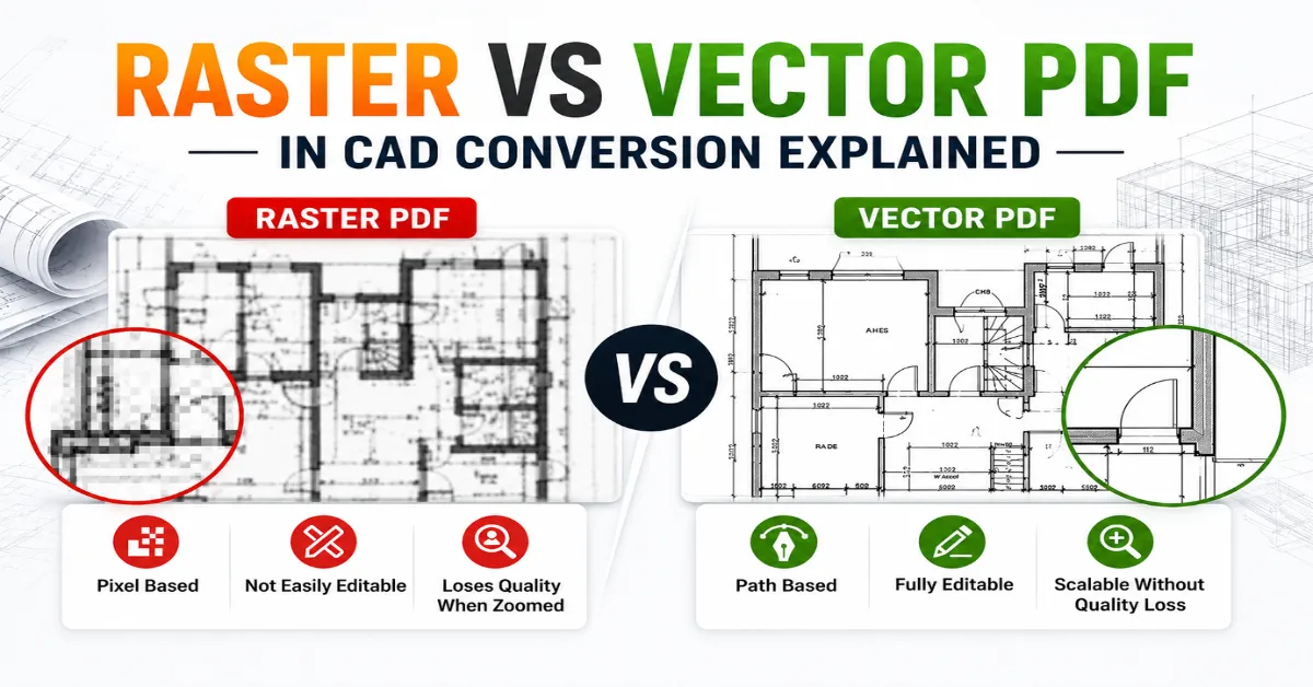
Diving into a Raster vs Vector PDF comparison might seem overly complex initially, but the foundational concept is pretty basic. One type is made of tiny dots, while the other relies on math paths and fully flexible lines. That single difference changes how drawings behave during CAD conversion.
Raster PDFs usually come from scanned documents. Antique hand-drawn designs, field sketches, paper layouts, or physical sheets run through an office scanner typically make up this group, highlighting the core traits of a scanned pdf vs vector pdf. Zooming into a raster file feels similar to zooming into a low-quality social media screenshot. Edges become blurry, dimensions lose sharpness, and line clarity drops quickly.
Modern files operate on an entirely different level by locking in crisp lines, perfect arcs, true coordinates, and actual text data. These are typically generated directly from design platforms like CAD or Revit, meaning they keep absolute precision no matter how close you zoom in.
When looking at raster vs vector pdf drawings, this fundamental split impacts your workflow more than you might guess. A line-based file lets you easily modify paths, isolate layers, and trace geometry, while dot-based files usually force you to rebuild or trace paths from scratch.
Drafting groups tackling raster pdf to cad conversion often run into major bottlenecks because messy sheets require intense cleanup. Speckles, faint lines, crooked pages, and scribbled notes muck up the process, whereas a vector pdf to cad conversion goes smoothly because the true geometry is already embedded.
Why Raster PDFs Create More Challenges During CAD Conversion
Flat image files definitely have an old-school aesthetic, but that visual style won’t save you when deadlines are crashing down. Most design software struggles to find true line paths on a flat image, meaning you have to put in far more manual drafting hours to convert raster pdf to dwg.
Think of raster PDFs as digital photographs of drawings rather than actual technical drawings themselves. Every wall line, dimension, hatch pattern, and symbol exists as a collection of tiny colored pixels. CAD software sees an image instead of editable geometry.
That creates several issues:
Problem | Raster PDF Impact |
Poor zoom quality | Lines become blurry |
Difficult editing | Objects are not editable |
Low conversion accuracy | Auto-tracing errors occur |
Large file cleanup time | Manual correction required |
Text recognition issues | OCR mistakes appear |
The biggest headache appears during the conversion of raster pdf to dwg projects. Automatic conversion tools often struggle to identify overlapping lines or faded details. A slightly skewed scan can completely distort scaling inside CAD software.
Managing written notes is another frequent headache since building prints are packed with room names, dimensions, and callouts. Flat scans often cause automated tools to break words apart into random vector shapes or garbled lines. That means additional drafting time and higher project costs.
Interestingly, many companies still depend heavily on raster files because historical drawings exist only in paper format. Massive civil works, historic renovations, and older city archives are full of these scanned pages. Because automated tracking software struggles with them, having a skilled drafter on hand is the only real way to get clean results.
One practical industry guide from Autodesk explains how vector geometry improves drafting precision and editing workflows inside AutoCAD environments.
Also read: Common PDF to CAD Challenges and Their Solutions
The Real Strength of Vector PDFs in AutoCAD
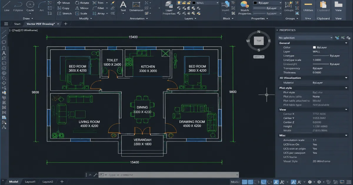
Vector files behave like disciplined professionals inside a CAD workflow. Clean. Organized. Predictable. The difference becomes obvious within seconds of opening the file.
A vector pdf in autocad maintains crisp geometry because the file contains actual mathematical drawing information. Every line has coordinates. Every curve has direction. Every text element exists as editable data instead of image pixels.
That dramatically improves conversion quality.
Instead of tracing blurry walls manually, CAD software can directly interpret vector paths into editable DWG geometry. The ultimate output turns out cleaner, quicker, and infinitely more useful. Designers and engineers naturally lean toward path-based files because the scale and proportions remain perfectly locked in from start to finish.
Another major advantage involves layer management. Many vector PDFs preserve layer structures from the original CAD file. That means walls, dimensions, electrical layouts, and annotations can remain organized after conversion.
The productivity difference becomes huge on large projects. A clean vector pdf to cad conversion might take minutes, while raster-based redrafting could consume hours or even days.
Here is where Raster vs Vector PDF becomes especially important for BIM workflows. Modern Scan to BIM and CAD teams often receive mixed drawing sets. Some files are exported vectors. Others are scanned rasters. Identifying the file type before starting conversion prevents workflow disasters later.
Another hidden advantage involves scalability. Vector drawings stay sharp regardless of zoom level or print size. That matters heavily for fabrication drawings, shop drawings, and high-detail construction documentation.
Raster vs Vector PDF Drawings: Visual Differences That Matter
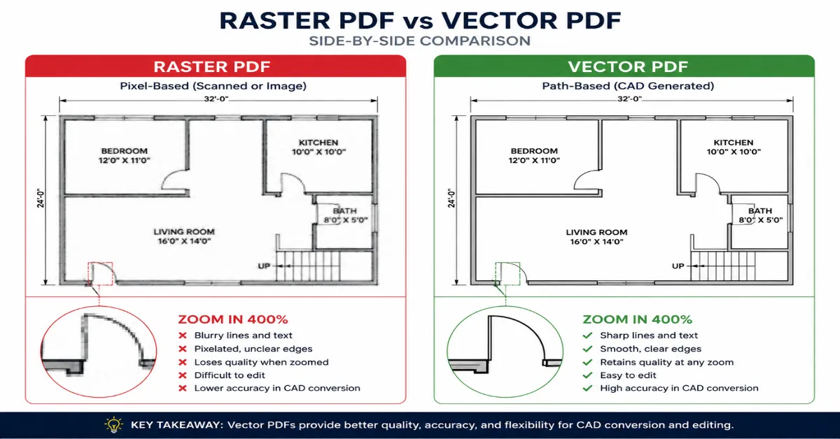
Most people notice the difference between raster and vector drawings only after zooming in. That is usually the “aha” moment.
Raster images break into visible squares because they rely on pixels. Vector drawings stay smooth because they use equations and paths instead of fixed image dots. It sounds boring on paper, but inside CAD production, the difference feels massive.
The contrast becomes even clearer during editing. In raster vs vector pdf drawings, vector files allow direct object modification. Lines can stretch. Text can update. Shapes can move without losing quality. Raster files behave more like locked screenshots.
A quick comparison explains it better:
Feature | Raster PDF | Vector PDF |
Built with | Pixels | Mathematical paths |
Zoom quality | Loses clarity | Remains sharp |
Editable in CAD | Limited | Fully editable |
File source | Scanned drawings | CAD-exported files |
Conversion quality | Moderate | High |
DWG accuracy | Lower | Higher |
This distinction becomes critical in engineering industries where precision matters. A tiny scaling mistake inside a raster conversion can affect measurements, fabrication, or construction coordination later.
Interestingly, many project managers overlook this issue during the file submission stages. Teams exchange PDFs, assuming every file behaves similarly. Then chaos quietly enters during CAD drafting.
The safest workflow usually starts with identifying whether the source drawing is raster or vector before conversion begins. That simple step prevents countless revision cycles later.
Also read: PDF to CAD Conversion for Engineers: A Complete Guide
Scanned PDF vs Vector PDF
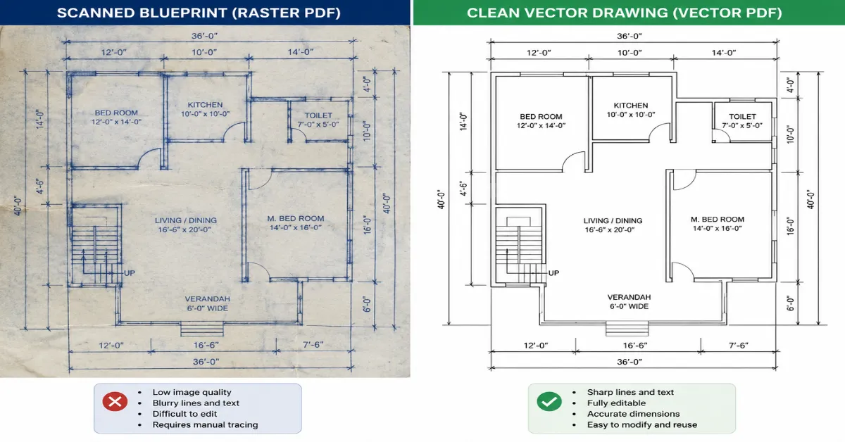
The battle between scanned PDF vs vector PDF appears constantly in architecture, construction, and manufacturing projects. Both formats exist everywhere, but only one consistently supports efficient CAD conversion.
Scanned PDFs mainly exist because physical drawings still dominate older project archives. Historical construction records, municipal blueprints, and renovation layouts often survive only through scanning. These files preserve visual information, but they lack editable intelligence.
Vector PDFs, however, are digitally generated from CAD software itself. That means the original design data remains embedded inside the file structure. CAD programs can interpret that information more accurately during conversion.
For engineering projects, precision usually decides the winner immediately.
A vector file supports:
- Accurate dimensions
- Cleaner geometry
- Better line recognition
- Easier editing
- Faster DWG generation
Meanwhile, scanned PDFs often require:
- Image enhancement
- Noise cleanup
- Scale correction
- Manual tracing
- OCR adjustments
That does not mean raster files are useless, far from it. In renovation and legacy projects, raster drawings often provide the only available reference material. Skilled CAD teams simply adapt the workflow accordingly.
One surprising reality appears during large-scale conversion projects. Hybrid workflows are becoming common. Some sheets inside a drawing set may be vector-based, while others remain scanned rasters. Experienced drafting teams separate files before processing to improve accuracy and turnaround time.
How CAD Software Handles Raster vs Vector PDF Conversion
Software plays a huge role in the Raster vs Vector PDF discussion, but software alone cannot magically fix poor source files. That expectation causes disappointment more often than people admit.
Most CAD platforms support PDF import today. Standard industry programs can read math paths directly out of incoming documents. The moment you import these sheets, your drawing tool instantly translates those paths into editable lines, arcs, and circles.
Raster files behave differently.
Instead of recognizing editable paths, CAD software imports raster drawings as images. That means the drafting process usually involves tracing or semi-automatic vectorization.
Some tools attempt automatic raster recognition, but results vary depending on scan quality. Dark shadows, wrinkles, tilted pages, faded ink, and overlapping annotations confuse conversion engines quickly.
The workflow generally looks like this:
Vector PDF Workflow
- Import PDF
- Detect geometry
- Convert lines and text
- Save as DWG
Raster PDF Workflow
- Import scanned image
- Clean image quality
- Trace geometry manually
- Correct scaling
- Save as DWG
The time difference can become dramatic on large projects.
That is why experienced CAD professionals evaluate source quality before promising turnaround timelines. A clean vector file might finish quickly, while a poor raster scan may require extensive manual reconstruction.
Common Mistakes During Raster PDF to CAD Conversion
Some conversion problems repeat so often that they almost deserve their own warning labels. Most errors happen because the source file quality gets ignored at the beginning.
One common issue involves low-resolution scans. Microscopic dimensions and detailed cross-hatching completely blur out if the base scan quality is subpar. Plus, if a sheet gets pulled through a scanner slightly crooked, that tiny rotation can throw off your scale and warp your dimensions inside the software.
Layer confusion also creates headaches. Raster files rarely preserve layer structures, so everything merges into a single flat image. That forces CAD drafters to reorganize the entire drawing manually.
Another overlooked mistake appears during automatic vectorization. Some software aggressively converts every pixel cluster into polylines. The result becomes messy geometry with thousands of unnecessary nodes. Editing such files later feels like untangling earphones from a pocket.
The smartest approach involves balancing automation with manual quality control. Human review still matters heavily in high-accuracy CAD conversion projects.
Choosing the Right Format for Better CAD Productivity
Productivity inside CAD environments depends heavily on source file quality. The smoother the input, the faster the workflow. That simple reality explains why vector-based documentation continues growing across engineering industries.
Vector files reduce drafting fatigue significantly. Clean geometry allows faster editing, accurate snapping, better plotting quality, and fewer PDF to CAD conversion errors. In large production environments, those small efficiencies save hundreds of working hours over time.
Flat graphic files aren’t going away anytime soon, particularly when dealing with building retrofits and old paper records. You just have to accept that they need serious prep work before they are ready for production.
Choosing between raster and vector formats usually depends on three factors:
Project Need | Recommended PDF Type |
High editing accuracy | Vector PDF |
Historical document recovery | Raster PDF |
Fast DWG conversion | Vector PDF |
Legacy blueprint conversion | Raster PDF |
BIM coordination | Vector PDF |
Modern design workflows increasingly prioritize vector-first documentation because digital collaboration depends on precision and scalability.
The future also points toward smarter AI-assisted conversion systems, but even advanced software still performs better when clean vector data exists from the start.
Conclusion
The difference between Raster vs Vector PDF affects far more than visual quality. It fundamentally dictates how accurate your files are, how fast you finish, and your overall project output. Image files give you a visual picture to look at, while path files give you raw, editable data to work with—and that changes your whole game.
Old scans remain a fixture for additions and historical work, but clean digital paths rule modern design offices because they are faster to alter and way sharper. Grasping the differences inherent in Raster vs Vector PDF protects you from project lag, bad scales, and irritating drafting fixes.
For teams managing building blueprints, manufacturing schematics, or structural models, picking the right processing route saves massive amounts of time and budget. Bringing in specialized drafting support ensures crisp layouts, spot-on file exports, and smooth project handovers without infinite redrafts.
Need accurate raster pdf to cad conversion or vector pdf to cad conversion services? Contact us today and get a fast quote for reliable CAD drafting support tailored to project requirements.
Frequently Asked Questions