Table of Contents
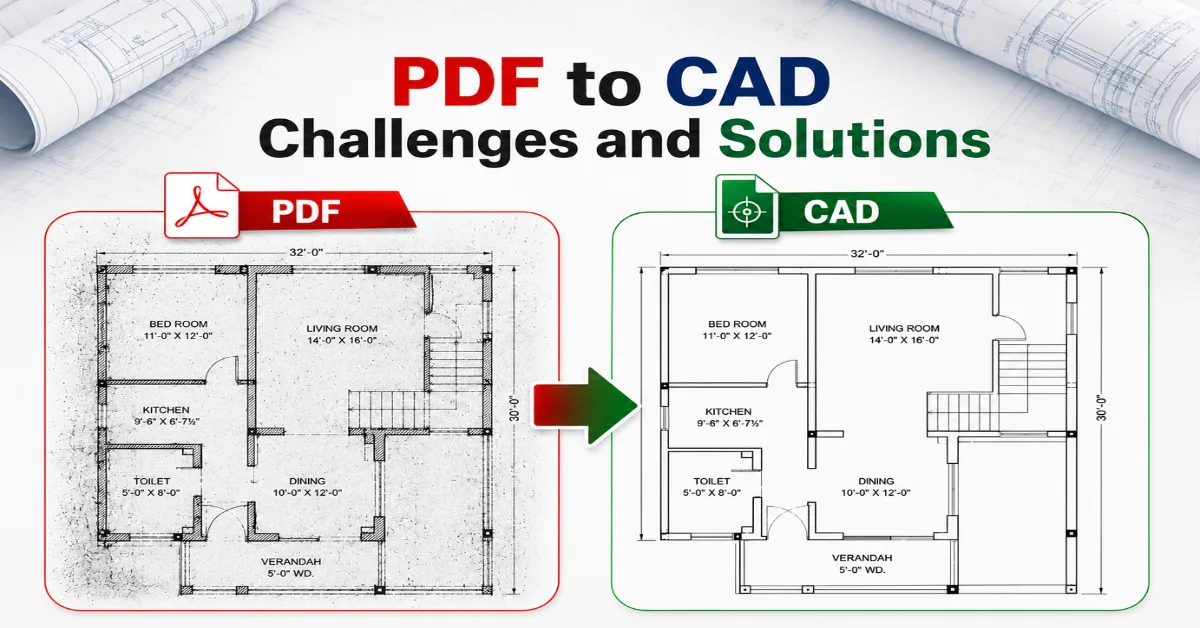
ToggleDigital drawings may look clean and polished on screen, yet the moment a PDF enters a CAD workflow, chaos sometimes walks in wearing steel-toe boots. Lines shift. Layers disappear. Dimensions suddenly behave like rebellious teenagers. That is exactly why PDF to CAD challenges remain one of the biggest headaches in architecture, engineering, construction, and manufacturing projects across the USA.
A smooth conversion can save hundreds of work hours. A poor one can quietly damage an entire project timeline. From scaling issues in CAD conversion to low-resolution PDF to CAD conversion problems, even a tiny oversight can blow up into pricey project revisions down the line. Fast-moving engineering sectors heavily rely on precise CAD data extraction and clean DWG setups to keep their field operations running without hitting a wall.
Modern companies do not look at this as a basic file swap anymore. It is a highly precise process where formatting clarity, readability, and clean file structures are just as critical as hitting a fast turnaround deadline.
Why PDF to CAD Conversion Matters More Than Ever
Construction and design teams today operate inside extremely tight schedules—every second matters. A single missing line in a converted drawing can create confusion between contractors, engineers, and project managers. That is where PDF to CAD challenges begin affecting real business outcomes.
Tons of firms still get older legacy blueprints in PDF format from deep archives, client folders, or external vendors. The headache is that PDFs simply cannot be modified the way engineering files can, since drafting platforms need precise vectors, clean layer splits, exact measurements, and actual geometry—things flat documents were never meant to handle.
The real trouble starts when teams rush through converting bad files without pausing to verify the output. Out of nowhere, walls get crooked, critical symbols drop off the sheet, and dimensions stop matching real-life site conditions, which leads to problems converting PDF to DWG and nobody wants to deal with layout blunders like floating staircases due to an inaccurate CAD conversion.
The boom in building remodels, BIM coordination workflows, and 3D laser scanning has pushed up the market demand for highly precise vector files. Modern designers expect live, editable drafts that blend perfectly into their current toolsets instead of static layouts locked up inside uncooperative documents, adding to the list of PDF to CAD challenges.
Poor Quality PDF Drawings Create Major Conversion Problems
One of the most common PDF to CAD challenges starts with the source file itself. Many PDFs used in engineering projects are decades old, scanned multiple times, or compressed until they resemble blurry photocopies from another century.
You will find that poor quality PDF drawings frequently suffer from washed-out lettering, fragmented line work, ink smudges, crooked scans, and tangled symbols. When you run these through basic conversion software, the program cannot figure out what it is looking at, leading to dropped geometry, bent lines, and messy notes.
This issue becomes even worse when raster PDFs are involved. Unlike vector PDFs, raster files are image-based. Conversion software must guess where lines begin and end. That guesswork often creates CAD conversion errors that require hours of manual cleanup.
A cleaner source file dramatically improves accuracy. Getting high-res scans with crisp visual contrast makes it worlds easier for vectorization software to recognize shapes. Smart draftspersons also take the time to clean up files beforehand by de-skewing the pages, wiping away digital noise, and boosting contrast.
Around the seventh paragraph, one highly useful industry resource deserves attention for teams handling technical documentation regularly: Autodesk’s official website. Even advanced conversion tools cannot magically repair severely damaged files. Garbage in, garbage out still applies very aggressively in CAD workflows.
Scaling Issues in CAD Conversion Can Destroy Accuracy
A drawing without proper scale is like a pizza recipe without measurements. Disaster arrives quickly.
Scaling issues in CAD conversion remain one of the most frustrating problems for engineers and architects. During the import phase, blueprints often come through with mismatched scales, warped shapes, or totally wrong measurement units. A wall segment that should be twenty feet long can instantly turn into twenty inches on screen, which is a massive nightmare to catch after concrete has already been poured.
Several factors usually cause these errors:
Common Cause | Resulting Problem |
Incorrect unit recognition | Wrong dimensions |
Distorted PDF scans | Uneven geometry |
Missing reference points | Alignment issues |
Raster image conversion | Measurement inaccuracies |
Compression artifacts | Broken scaling data |
To bypass these scale slip-ups, savvy designers double-check key dimensions the second the conversion finishes. Checking a known reference point on the drawing allows you to verify accuracy before diving into actual production work.
Another clever trick is breaking massive layouts down into bite-sized sheets rather than forcing a software program to swallow huge, complex blueprints all at once. Large PDFs sometimes introduce hidden distortions across wide drawing areas.
A reliable quality-check process saves far more time than fixing broken geometry later. That lesson usually arrives after one painful project experience.
Layer Mapping Problems in AutoCAD Slow Down Entire Workflows
Imagine opening a beautifully organised architectural drawing only to discover every single element sitting on one chaotic layer called “Layer0.” Pure heartbreak.
Experiencing layer mapping problems in AutoCAD can completely tank your drafting productivity. Having structured layers is the only way teams can separate structural walls, electrical runs, plumbing, HVAC layouts, and notes into clean, selectable views. Without organised layers, editing becomes slow and confusing.
Many conversion tools fail to preserve original layer structures during PDF processing. In some cases, text merges with geometry. Hatch patterns blend into linework. Symbols appear on random layers without logic.
This creates enormous problems for collaborative projects where multiple disciplines rely on clean file organisation.
Common symptoms include:
- Mixed object categories
- Unnamed layers
- Duplicate geometry
- Hidden annotations
- Corrupted line types
Experienced CAD specialists usually rebuild layer structures manually after conversion when automation fails. Although time-consuming, this process improves long-term usability significantly.
Modern workflows increasingly depend on structured CAD environments because BIM coordination requires accurate data separation. Messy layers today often become expensive coordination problems tomorrow.
Low-Resolution PDF Conversion Problems Reduce Drawing Reliability
Some PDFs arrive looking like they survived a thunderstorm inside a fax machine. Unfortunately, software accuracy drops sharply when resolution quality falls apart.
Low-resolution PDF conversion problems typically produce jagged lines, broken curves, unreadable text, and inaccurate geometry detection. OCR systems struggle to identify characters properly, especially in engineering annotations containing technical abbreviations.
This chaos directly disrupts automated CAD data extraction because the translation software cannot tell the difference between actual building lines and background scan garbage, meaning a random ink speck can easily turn into a stray line segment.
Low resolution also creates problems with:
Issue | Impact |
Blurred dimensions | Wrong measurements |
Distorted symbols | Interpretation errors |
Pixelated curves | Rough geometry |
Poor OCR recognition | Missing annotations |
Broken line continuity | Manual redrawing work |
Because of this, plenty of design managers now mandate strict minimum resolution specs before taking on files for conversion, since cleaner source documents save endless hours of fixing mistakes later.
Digital filters can fix a messy background slightly, but heavily degraded blueprints usually require a person to hop in and draft them by hand. Pure automation hits a wall eventually, and real-world messes have a habit of reminding us that tech still has limits.
Complex Drawing Conversion Issues Require Human Expertise
Let’s face it, some drawings are incredibly stubborn to convert. Certain files are packed with tight mechanical parts, overlapping layouts, scribbled field notes, rare symbols, or fifty years of revisions piled on top of each other like a technical lasagna.
These complex drawing conversion issues tend to completely break automated programs because untangling the lines demands real engineering experience rather than basic image matching.
Industrial schematics, intricate wiring diagrams, and heavy mechanical layouts are always the most prone to generating messy errors in PDF to CAD during an automated run. Small mistakes inside these documents may affect fabrication, manufacturing, or installation processes later.
The biggest challenge appears when conversion tools attempt to interpret:
- Curved geometry
- Cross-referenced details
- Dense annotations
- Custom symbols
- Hand-marked revisions
Human review becomes critical here. Skilled CAD professionals identify inconsistencies that automation misses entirely.
To counter this, top-tier firms mix automated tracing tools with human quality control. They let the software do the heavy lifting with repetitive line work, but keep veteran technicians on hand to verify the dimensions and overall drawing logic when it’s done. That hybrid approach significantly reduces CAD conversion errors and improves final drawing quality.
CAD Data Extraction Challenges Affect Project Efficiency
Current design practices run on pure data. Blueprints are no longer just pictures to look at; they host active project intelligence tied directly to ordering schedules, material volumes, cost estimates, and BIM workflows.
Trying to pull out that data gets incredibly messy when the source PDFs come with messy layouts, fuzzy lettering, or choked layers of information piled together.
Common errors include dropped dimensions, garbled text strings, broken lines, and missing file data, all of which stall out estimating and planning teams trying to coordinate the job.
For industries like construction and manufacturing, poor extraction quality creates a ripple effect:
Workflow Area | Potential Impact |
Quantity takeoffs | Cost estimation errors |
BIM coordination | clash detection issues |
Renovation planning | Incomplete site information |
Fabrication drawings | Manufacturing inaccuracies |
Facility management | Missing asset data |
Setting up strict verification checkpoints keeps these slip-ups to a minimum, and premier conversion shops pair smart text recognition with human eyes to ensure the data pulls through correctly. A clean CAD file ultimately supports smoother collaboration across every project phase.
How Modern Technology Is Improving PDF to CAD Conversion
On the bright side, conversion tech has gotten a lot sharper over the last couple of years. Newer platforms utilize machine learning and advanced vector tracking to smooth over the most frustrating PDF to CAD challenges.
Newer programs can spot varying line weights, pick out standard symbols, read text fonts, and maintain geometric shapes far better than old legacy tools, sometimes even sorting parts into separate layers on their own. Still, automation alone does not guarantee perfection.
The best workflows usually combine:
- High-quality source PDFs
- Smart preprocessing methods
- AI-assisted conversion tools
- Human quality checks
- Final CAD validation
That combination dramatically improves accuracy while reducing project turnaround time. The industry is also shifting toward BIM-integrated workflows where converted CAD files become part of larger digital building ecosystems. Clean conversion standards, therefore, matter more than ever before.
Best Practices to Reduce PDF to CAD Challenges
A smoother workflow begins long before conversion starts. Prevention remains cheaper than correction in nearly every engineering process. Several best practices consistently reduce PDF to CAD challenges and improve final drawing quality.
Start With Clean Source Files
Sharp scans with proper contrast and alignment provide better geometry recognition. High-resolution vector PDFs deliver the best results.
Verify Scale Immediately
Checking dimensions right after conversion prevents major downstream errors. Reference measurements should always match original drawings.
Use Layer Standards
Structured layers improve coordination between engineering teams and reduce editing confusion later.
Combine Automation With Manual Review
Software accelerates workflows, but experienced technicians still catch important errors that machines overlook.
Maintain Quality Control Checklists
A standardised review process improves consistency across large projects and reduces revision cycles. Reliable workflows rarely happen by accident. Strong processes create strong results.
Conclusion
Technical drafting might look simple from the outside, but wrestling with PDF to CAD challenges remains a major thorn in the side for architects, engineers, and fabricators everywhere. From working off poor quality PDF drawings to battling scaling issues in CAD conversion, even tiny technical hitches can quietly derail schedules, inflate budgets, and cause friction between teams.
Getting a perfect file requires a lot more than just clicking a button on a software application. You need crisp source documents, structured handling, meticulous checks, and true drafting expertise to deliver a product you can actually trust on the construction floor.
Newer tech has definitely made the process faster and more precise, but at the end of the day, a successful project launch still hinges entirely on close attention to detail and old-fashioned quality control.
Companies that want to stamp out CAD conversion errors, clean up their automated CAD data extraction, and make their documentation workflows run smoothly need to prioritize total accuracy over cheap, fast shortcuts.
Stuck with messy legacy files and need dependable PDF to CAD conversion backup for your next big project? Drop us a line today to get expert support, fast turnarounds, and spot-on CAD drawings customized for your exact engineering specs. Reach out for a quick quote and keep your team’s workflow moving ahead without extra drafting loops or costly delays.
Also read: PDF to CAD Conversion for Engineers
Frequently Asked Questions
What are the biggest PDF to CAD challenges?
The biggest PDF to CAD challenges include scaling errors, layer mapping issues, inaccurate geometry, poor quality PDF drawings, and missing annotations during CAD conversion workflows.
Why do CAD conversion errors happen frequently?
CAD conversion errors usually happen because of low-resolution PDFs, distorted scans, overlapping objects, or incorrect software interpretation during PDF to DWG conversion.
How can scaling issues in CAD conversion be fixed?
Scaling issues in CAD conversion can be reduced by checking units, validating reference dimensions, and reviewing geometry immediately after file conversion.
What causes layer mapping problems in AutoCAD?
Layer mapping problems in AutoCAD occur when conversion tools fail to preserve original layer structures, causing mixed objects and disorganized CAD files.
Why are poor quality PDF drawings difficult to convert?
Poor quality PDF drawings contain blurry text, broken lines, and distorted geometry, making accurate CAD data extraction and clean DWG conversion much harder.